What should I build with this…#
It all started with a once-in-a-long-time offer from the 3D printing and CNC machining service, Weerg (not affiliated): try out their clear, translucent resin 3D printing for an astonishing price of 0€!1
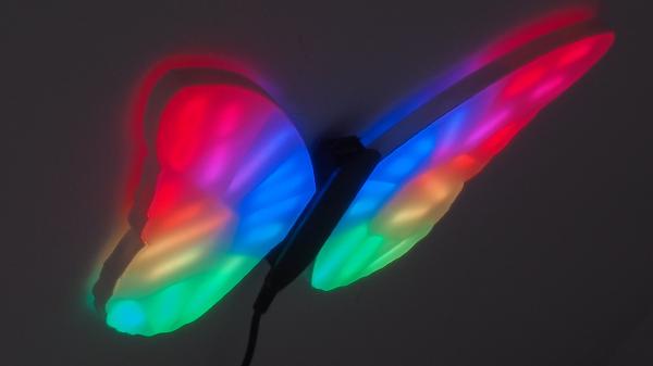
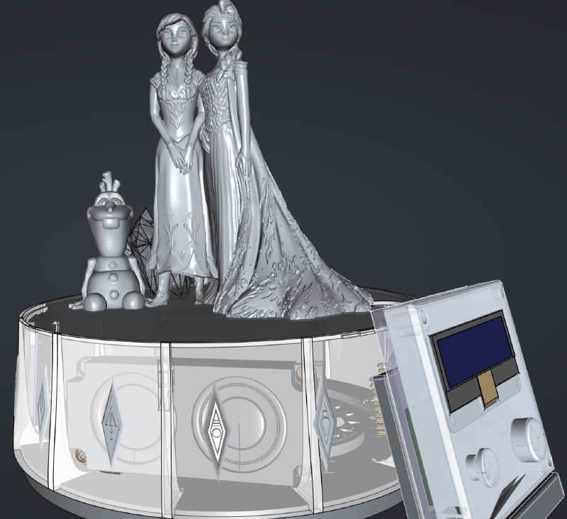
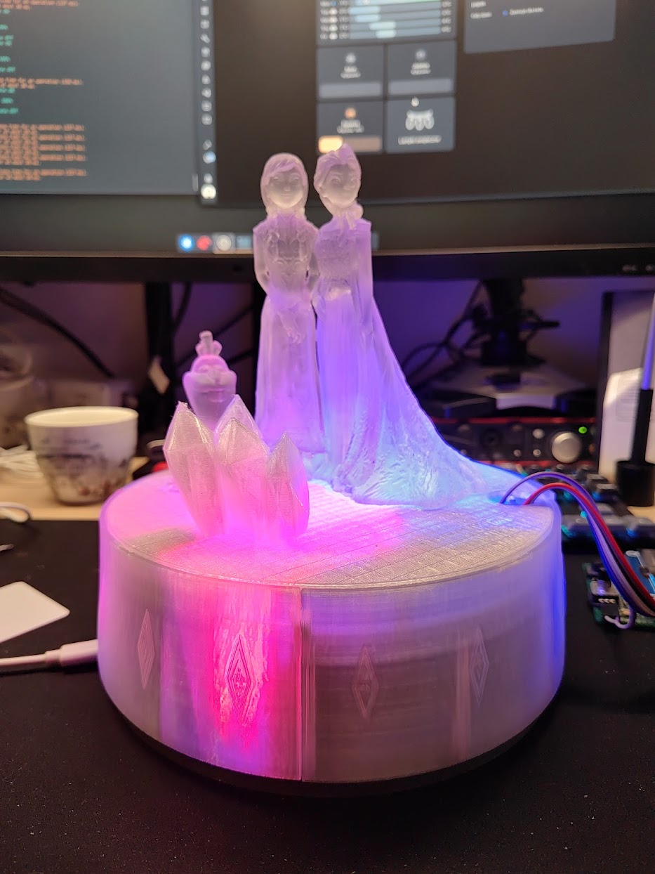
This was around the time I’d finished the RGB Butterfly, and I was looking to build another night light for the kid. At that time, she was heavily into the Frozen, so after a bit of Internet searching I found this beautiful model.
This was too much of an opportunity to pass up on…
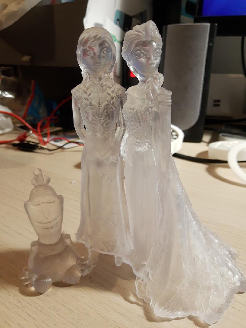
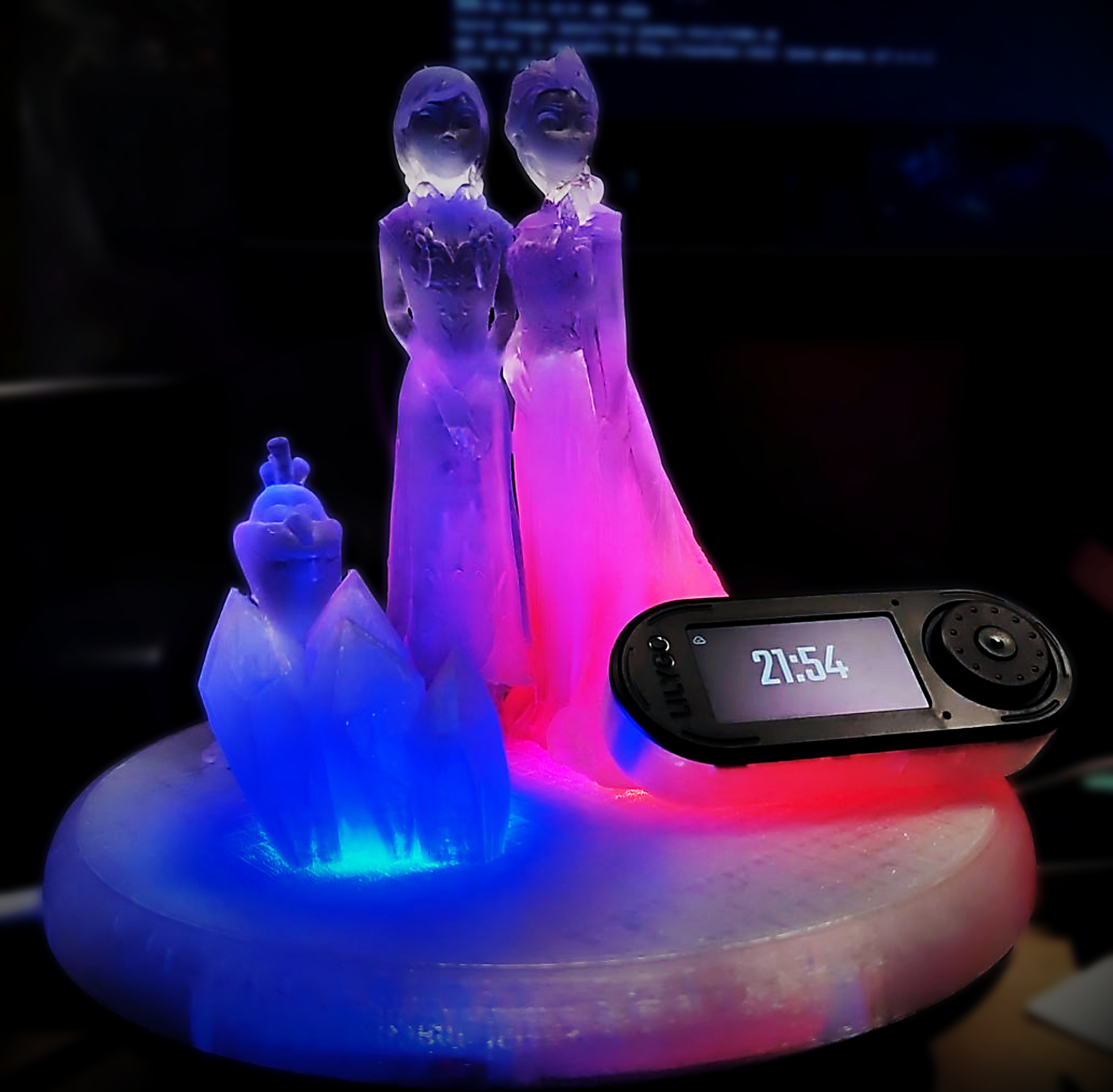
Translucent materials like that make for beautiful night lamps. The fact that the print looks like an ice sculpture is an added bonus. Also, if you look at the base of the 3D printed figurine, it is roughly based on two circles with diameters that just happen to match NeoPixel LED rings…
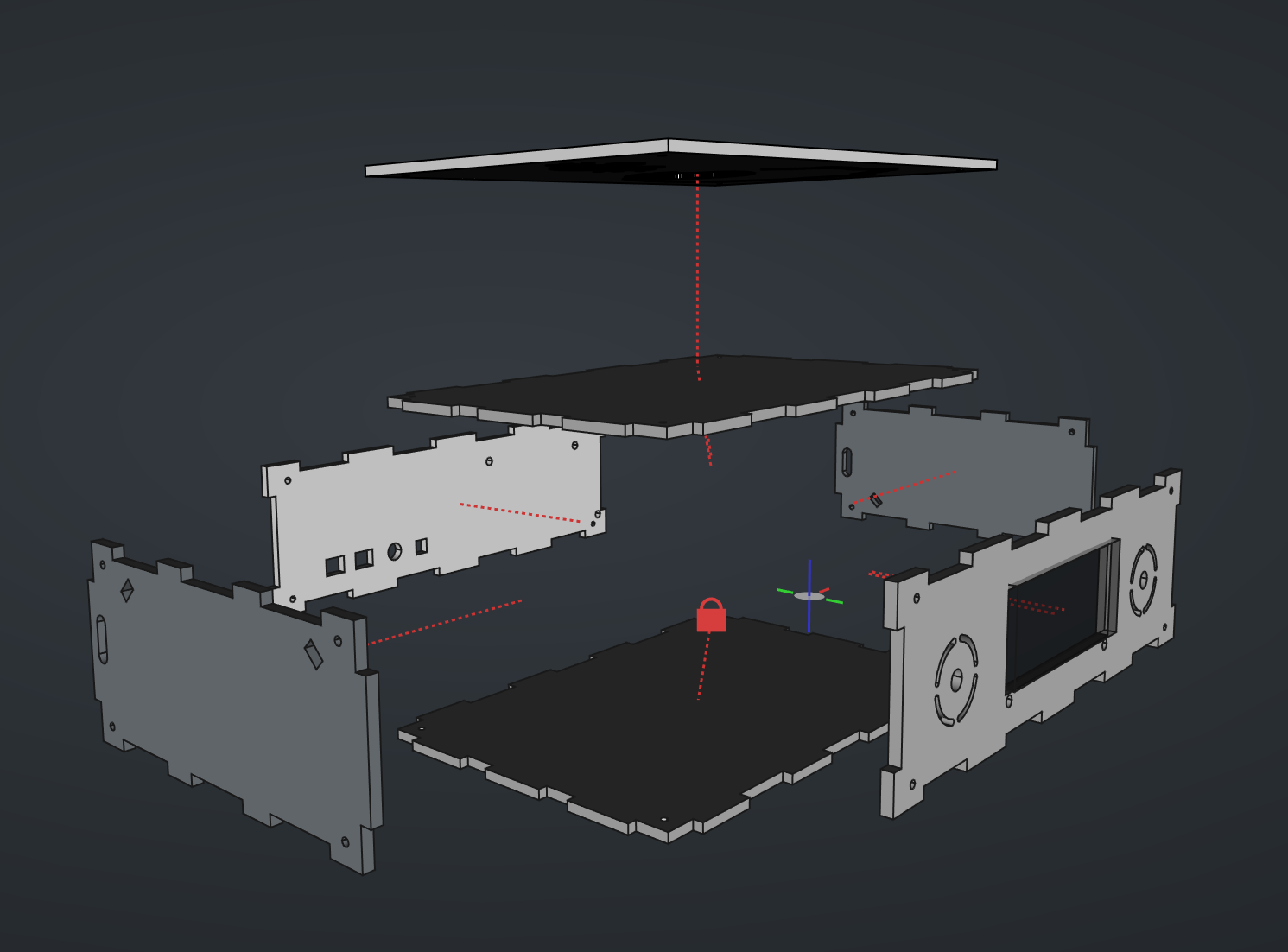
So the first idea was simple: create a basic base for the figurine from opaque (or ~30% transparent) plexiglass, with the top plate cut out to fit the 3D print. This way light would shine mostly through the print.
Then, inside the base, place a basic DC-DC power supply so that the LEDs in the ring would get enough current, connect an ESP32 development board, maybe even attach a small OLED screen to display the current time. Easy-peasy, in and out, 20 minute adventure, right?
However, what about local control of the lights? A night light really needs a button of some sort so it can be turned on or off, dimmed, brightened. Maybe even allow for a color change? Why use addressable RGB NeoPixels if they’d only be used with a single color?
The easiest solution to the local control problem is to use an IR receiver diode. Single part, a few pins, can be adapted to any of the generic IR remotes lying around. Having a switch that physically cuts power to the device is always a plus. This leads to the following bill of materials:
- ESP32 development board (e.g., NodeMcu v2 or any of its clones),
- OLED display module (I picked Waveshare’s 2.23inch OLED HAT),
- lever switch (bistable),
- IR receiver diode (e.g., VS1838B),
- two RGB LED rings, one with 12, the other with 16 WS2812 diodes.
- lever switch (for power)
Note that depending on the manufacturer, the LED rings might have different diameters, even with the same number of LEDs. I used ones with the outer diameter of 37mm (12 LED one) and 68mm (16 LED one).
…a nightlight?#
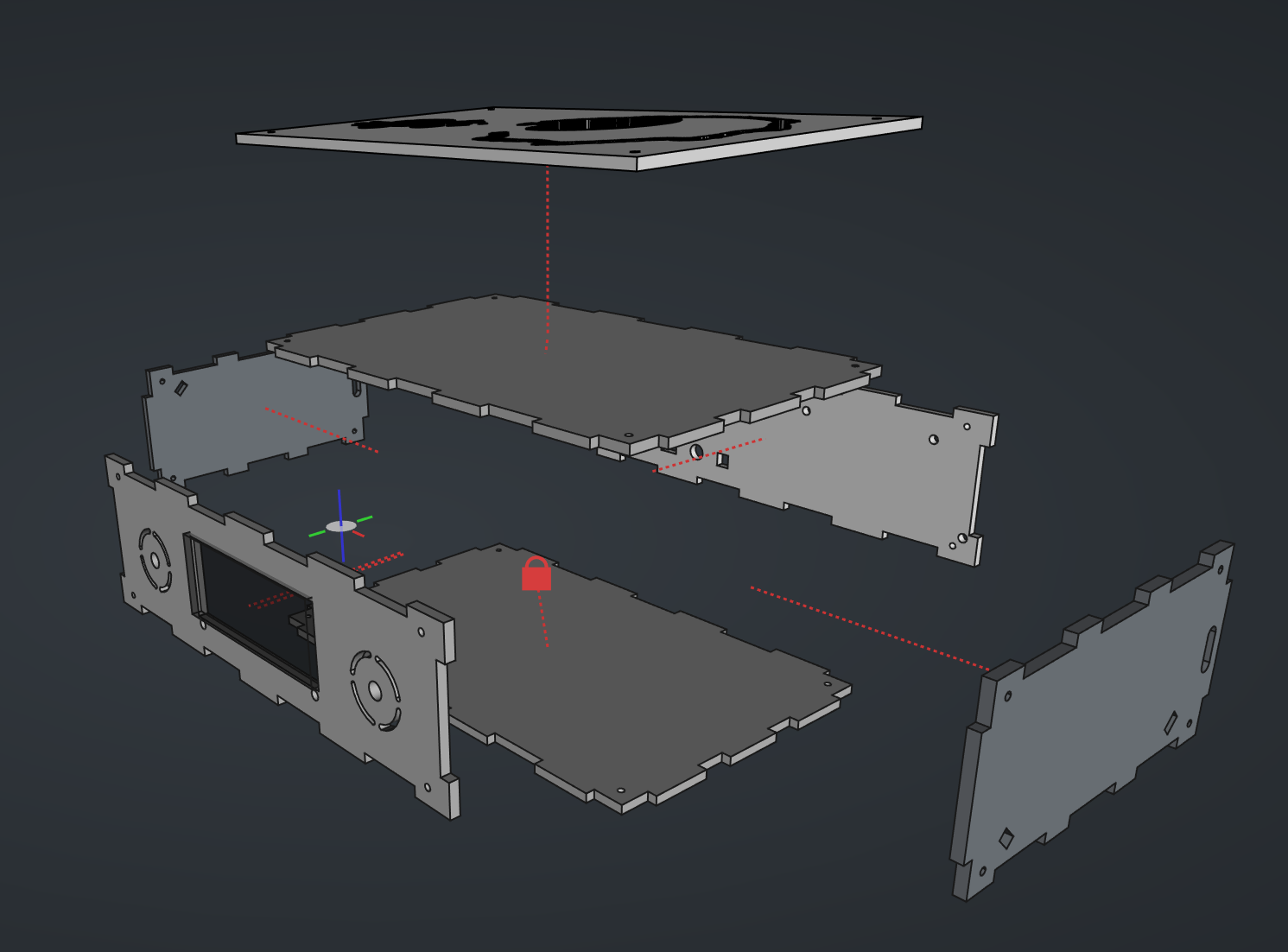
For the nightlight’s base I used the technique typically used in building wooden laser-cut boxes, makes assembly a lot easier. Laser-cut plexiglass doesn’t fit together as well as the wood does though; maybe that was just a matter of technical capabilities of the shop I ordered the cuts in.
With the help of a few 3D printed (using a 3D pen) connectors and some screws I could make the whole case solid enough that I was confident about giving it to a child.

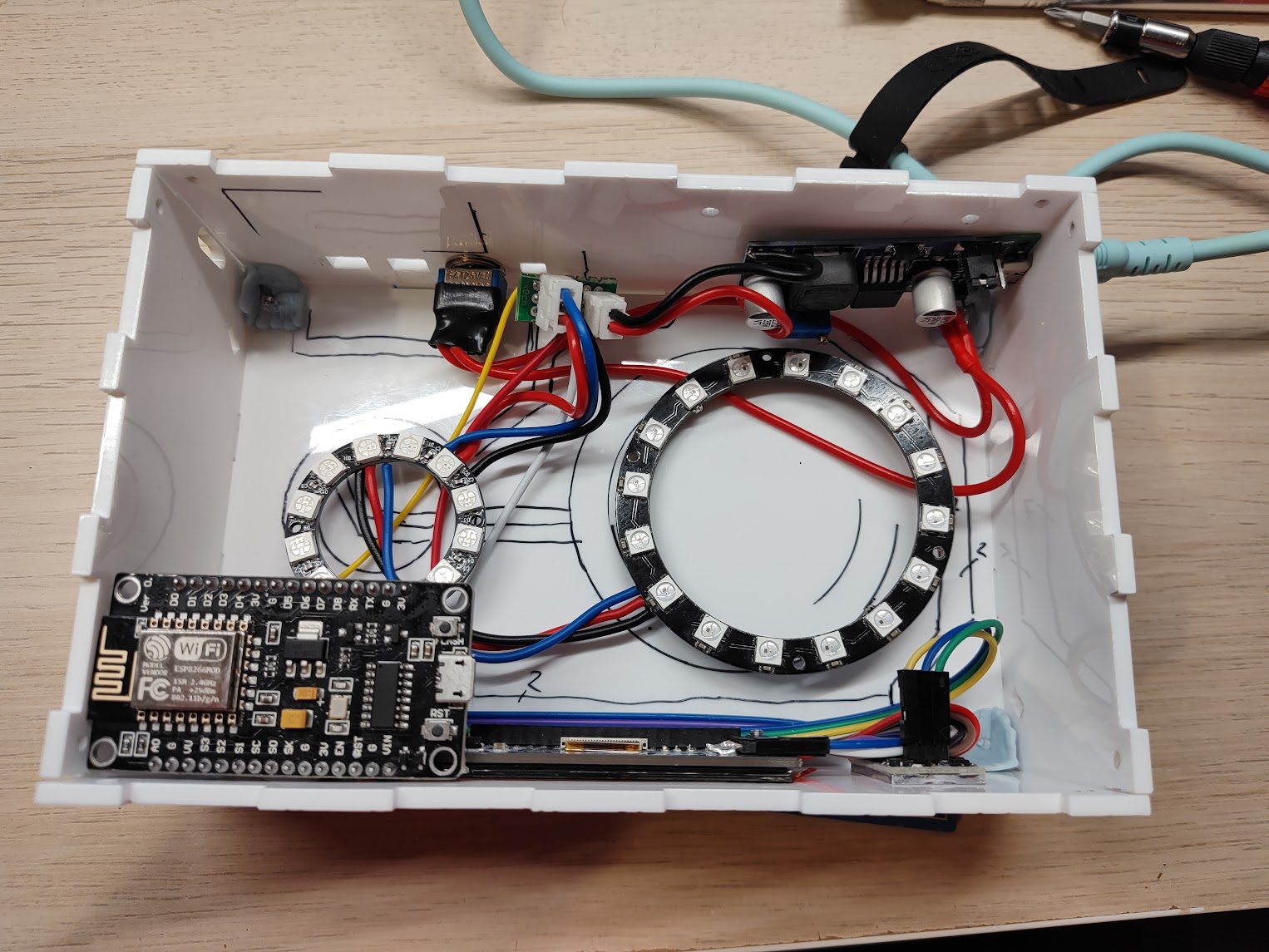
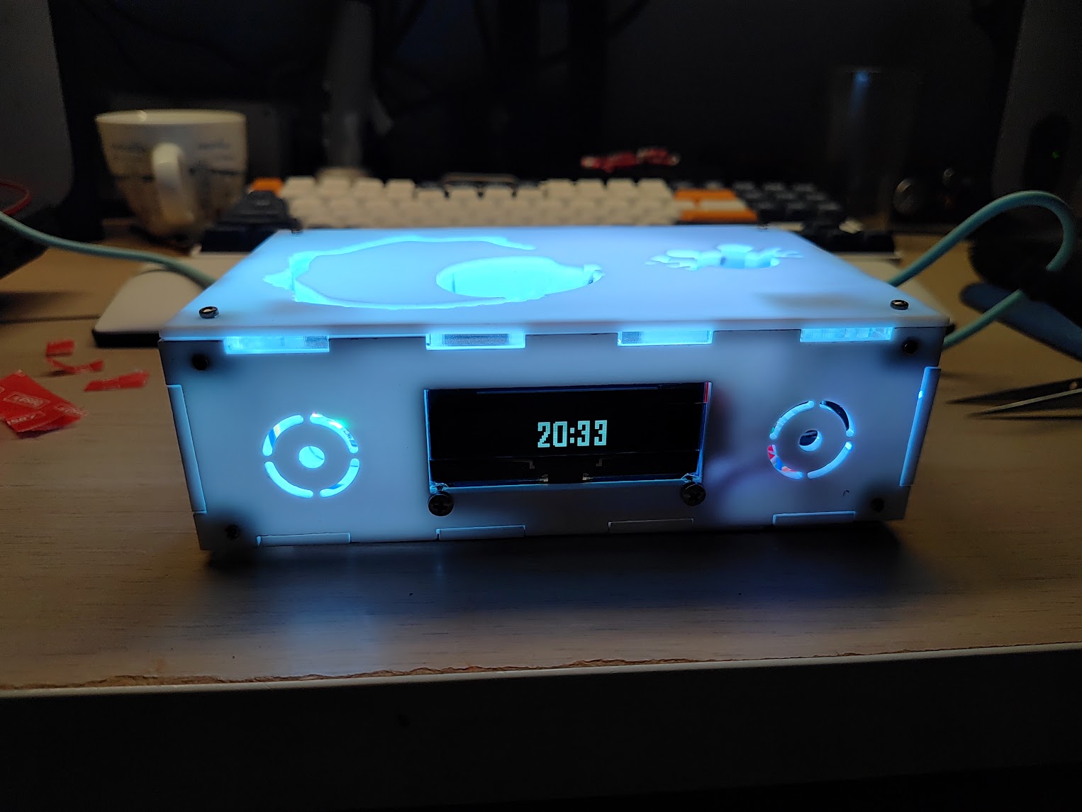
With a few lines of ESPHome configuration magic I had a working nightlight. Didn’t even have to use an ESP32; older ESP8266 was enough to control a few dozen LEDs.
While designing the front plate I did make a couple of circular cutouts. At first, I thought that I’d just add smaller LED rings behind them, but once everything was assembled, the cutouts started to look oddly similar to speakers…
…a music player?#
These cutouts just demanded to put speakers behind them. However, this required some design changes. For starters, ESP8266 doesn’t have enough processing power to simultaneously drive RGB LEDs and handle the music. ESP32 is a must, (and I later learned that it should be one of the newer models, with PSRAM).
To drive the speakers, an audio DAC with amplifier is needed. I picked up a tiny breakout board with a MAX98357A (not affiliated) D-class audio amplifier with I2S interface. ESPHome supports I2S natively, so integrating it with the ESP32 board should be straightforward.
I do believe that every connected (smart, if you will) device needs a local control option. Clouds may go offline, IR remotes tend to magically disappear2. That’s why I also tried to cram in two additional touch buttons with integrated lights, place them in the corners, above the speakers.
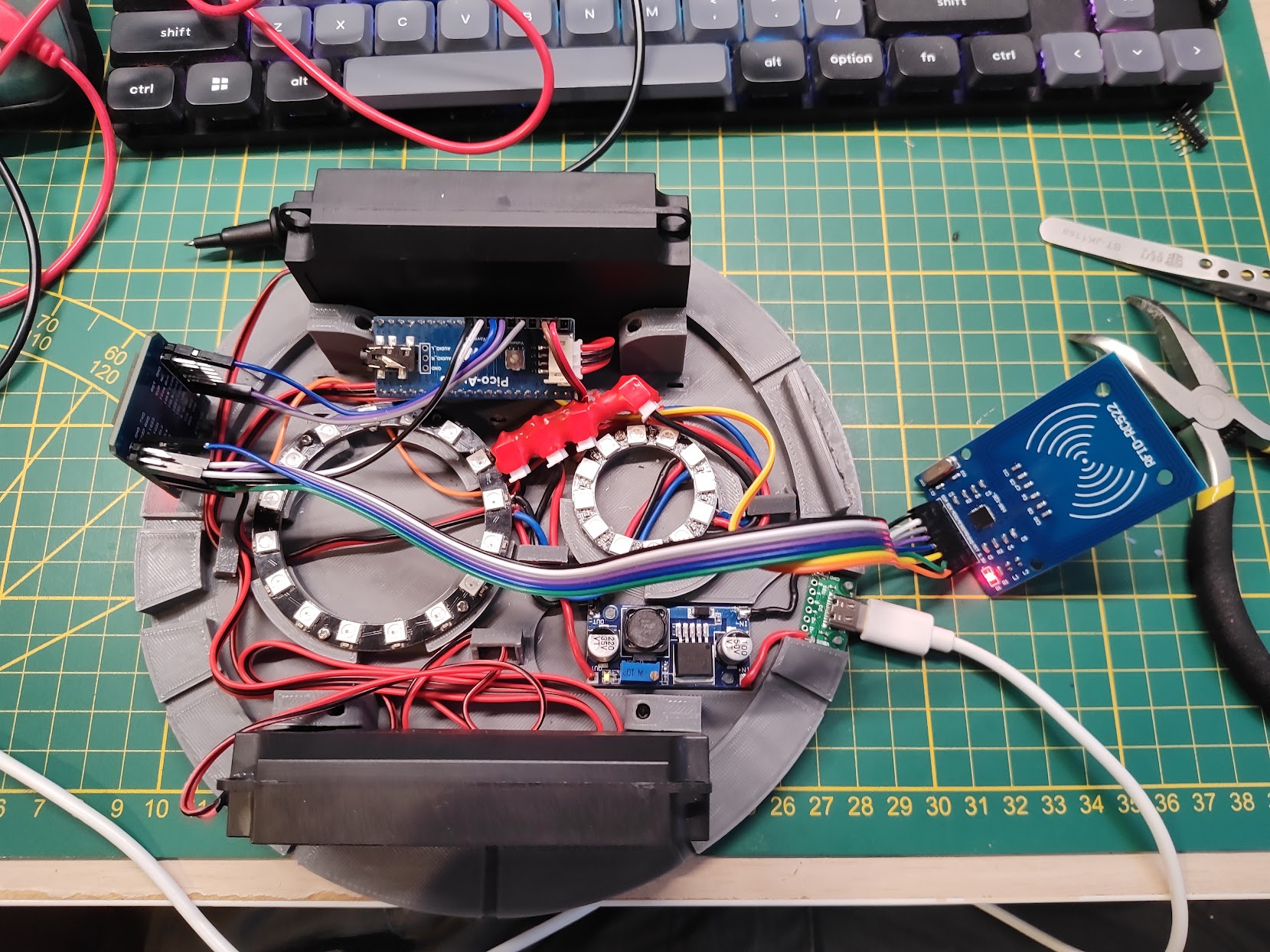
That’s when I also remembered the RFID Jukebox project. Seems like an awesome idea, let’s add a NFC reader module.
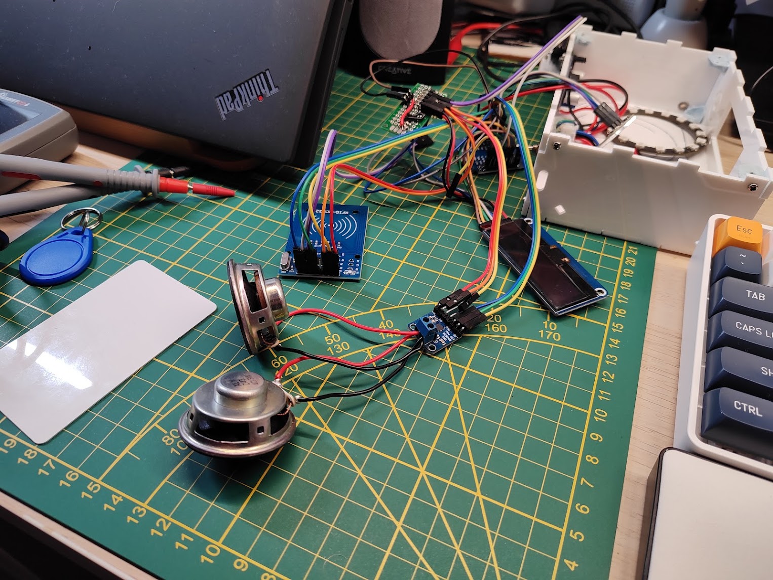
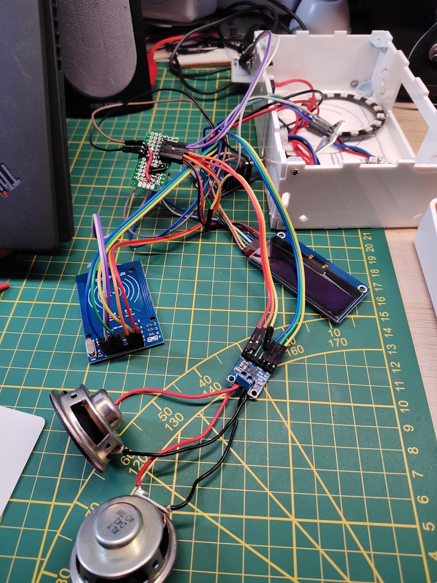
Trying to fit all the cables inside – horror. Every time I thought I had fit everything in place, it turned out that something broke (a wire, typically). So, here came the first learning:
PCB is typically better than a spaghetti of wires.
When deciding to work with Arduino-style module and breakout boards, make sure you either have an assortment of wires, or you are best friends with a wire crimper3.
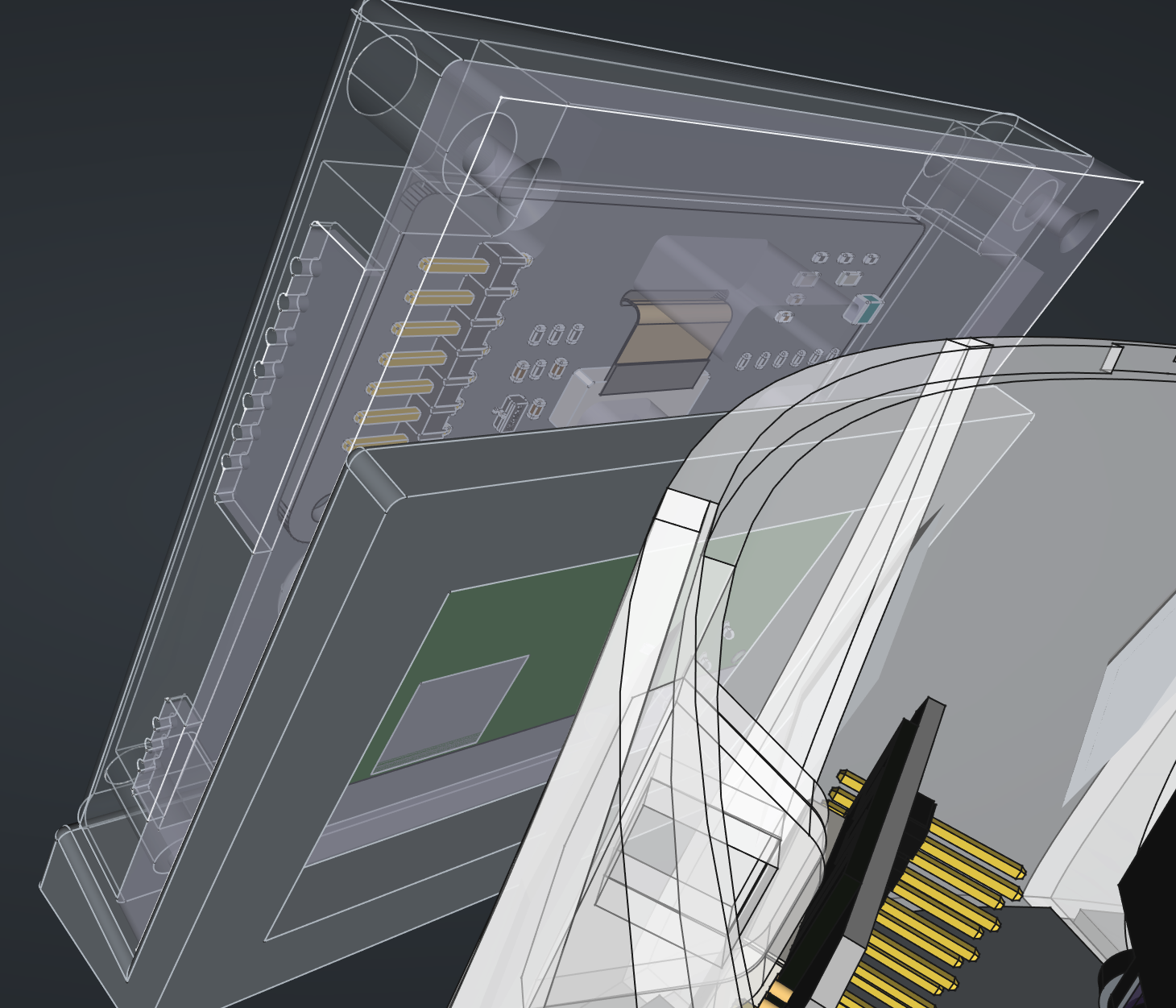
At this stage I was so fed up with the wires, I decided to design myself a breakout board that would fit behind the speakers and attach an RFID reader module on one side, and the ESP32 on the other.
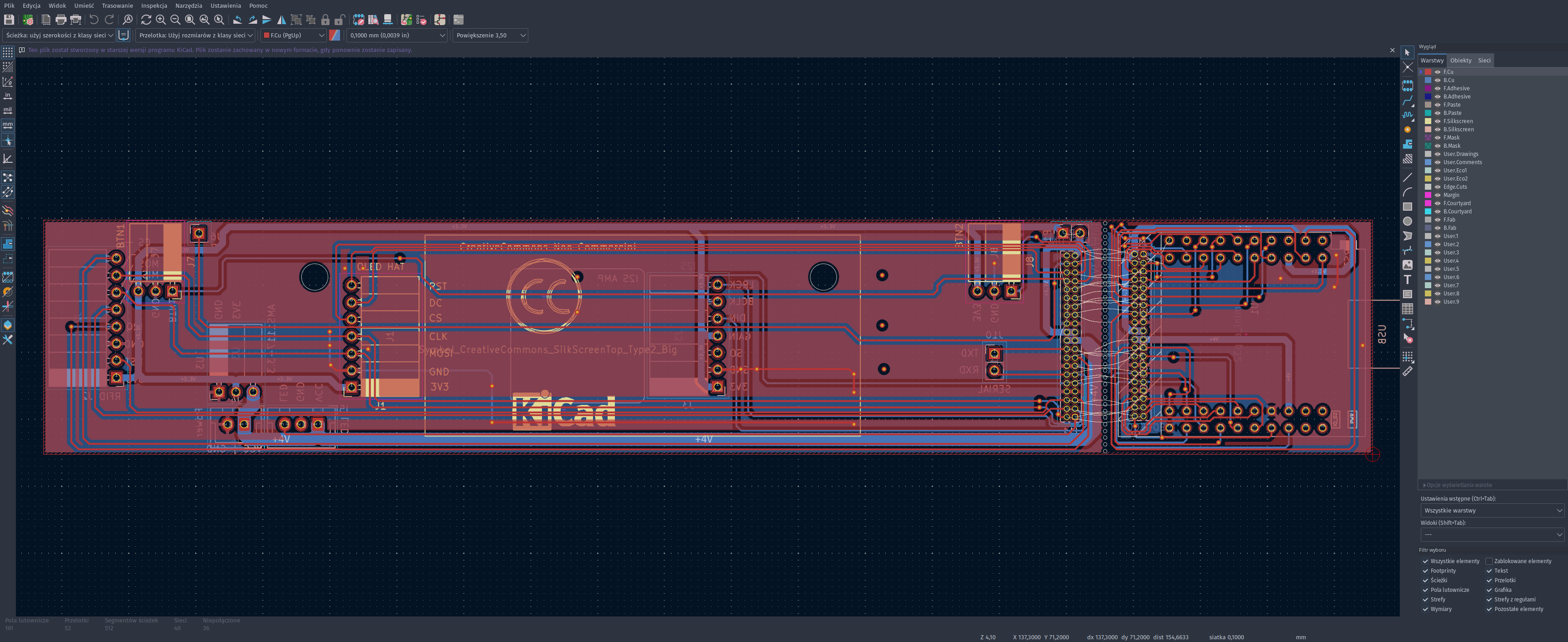
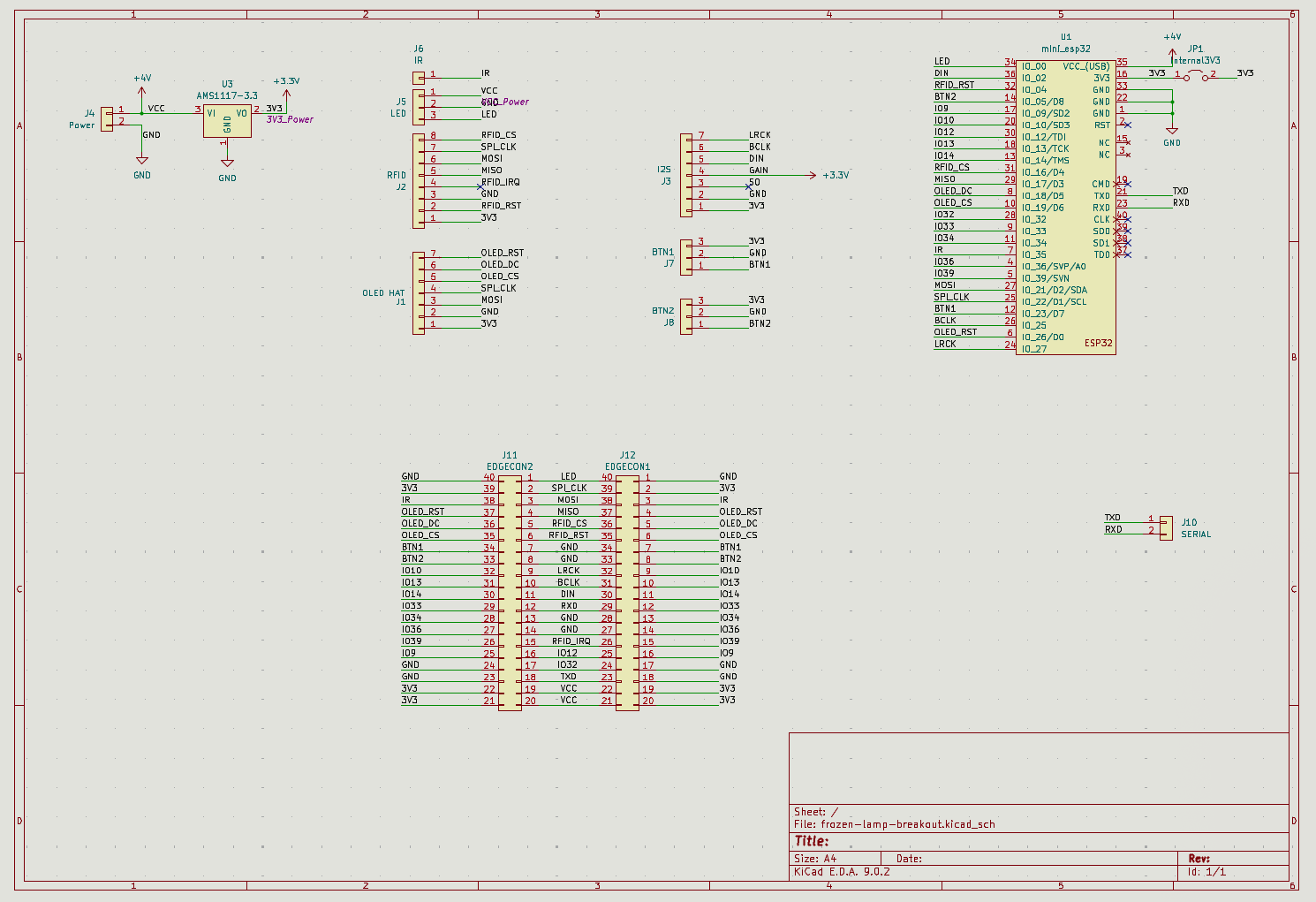
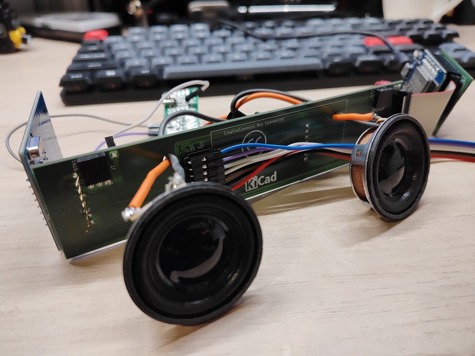
The breakout board had connectors for the audio amp, the OLED screen, and no wires! However:
Do not design a case with a tight fit, because it won’t fit.
Yes, the case turned out to be too small as I underestimated how much space should I leave for connecting the side boards. The ESP32 was connected with a tape connector which gave some leeway, but the RFID was supposed to be a solid goldpin connection. Not even going to mention that the touch buttons wouldn’t fit above the speakers. Which led to another truth:
Do. Not. Rush. To. The. Assembly.
Had I spent some more time modelling and fitting all the components inside the case, it might even work: properly fit in the case, provide a stable connection for all the components. Suffice to say that it didn’t.
Also, the breakout board was a bit of a hurried bust. Another truth came out of the woodwork:
Spaghetti of wires is better than PCB if the PCB doesn’t work.
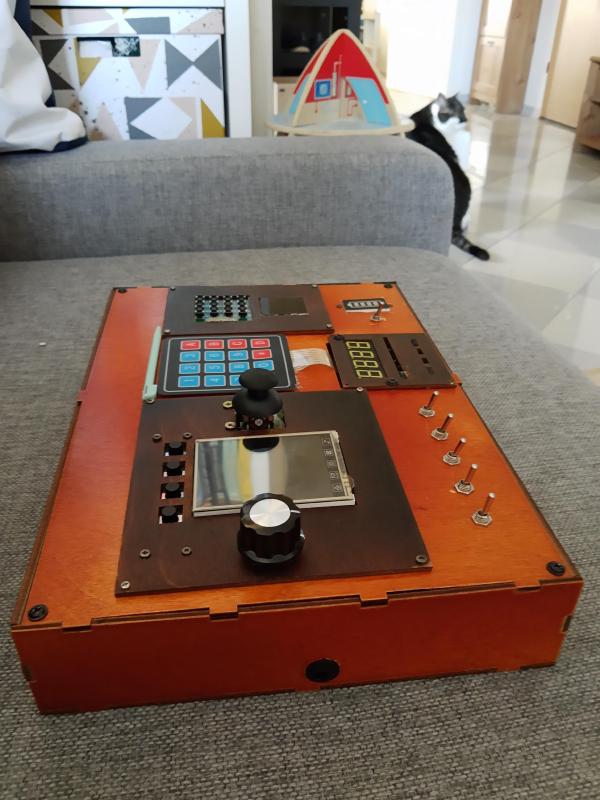
…a bigger music player?#
It was time for a do-over. Create a case from the ground up, fully 3D-printed, slightly larger than the previous one to fit all the components. And round4.
I also needed some new components. The project was once again using the Arduino module approach, but I was determined to make it work. New components included:
- Waveshare’s Pico-Audio hat for RPi Pico5.
- a decent DC-DC converter (not affiliated) for stable power supply.
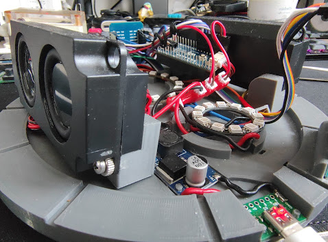
- two 5W speakers bundled with the Pico-Audio
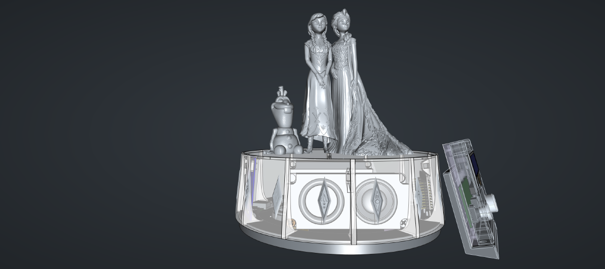
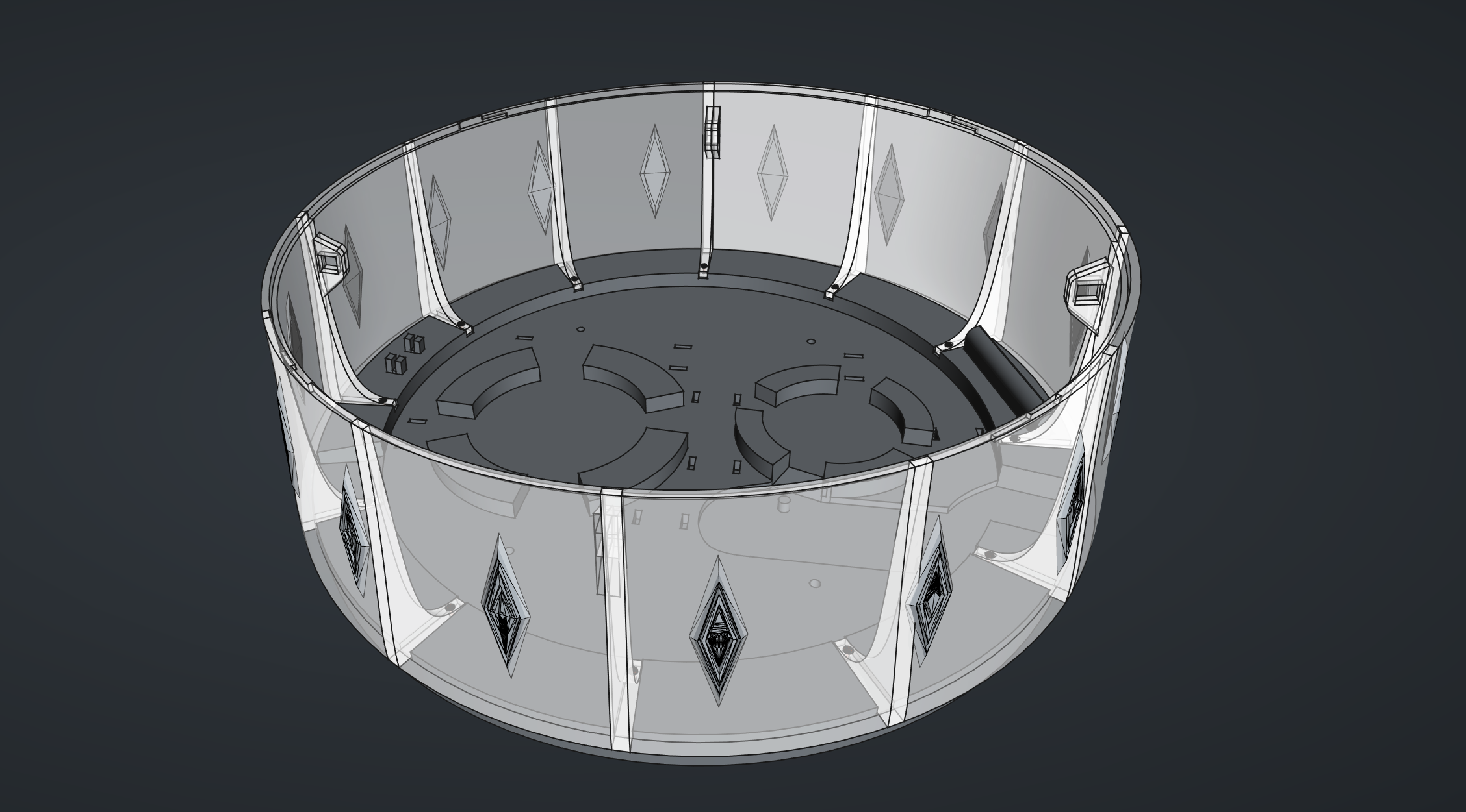
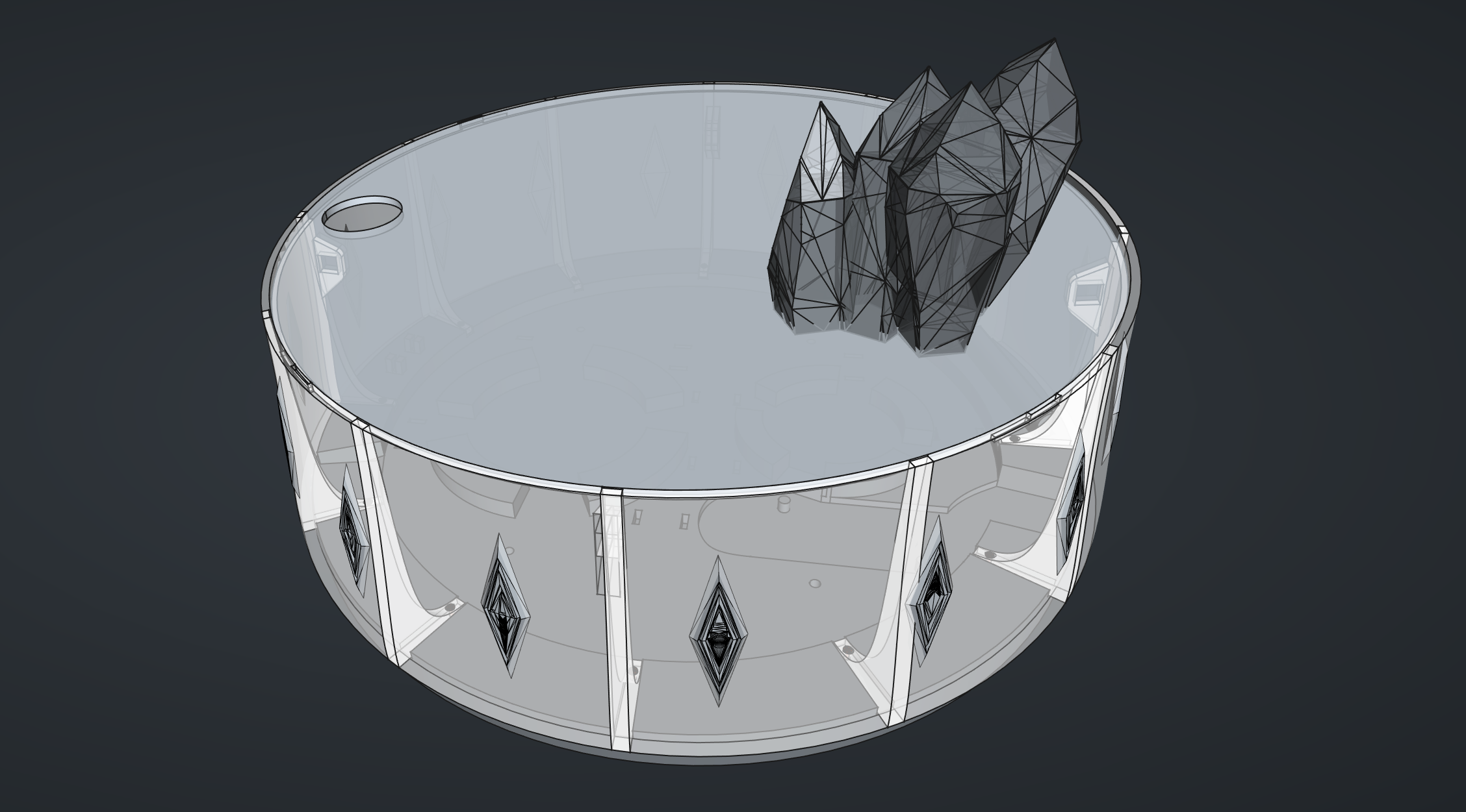
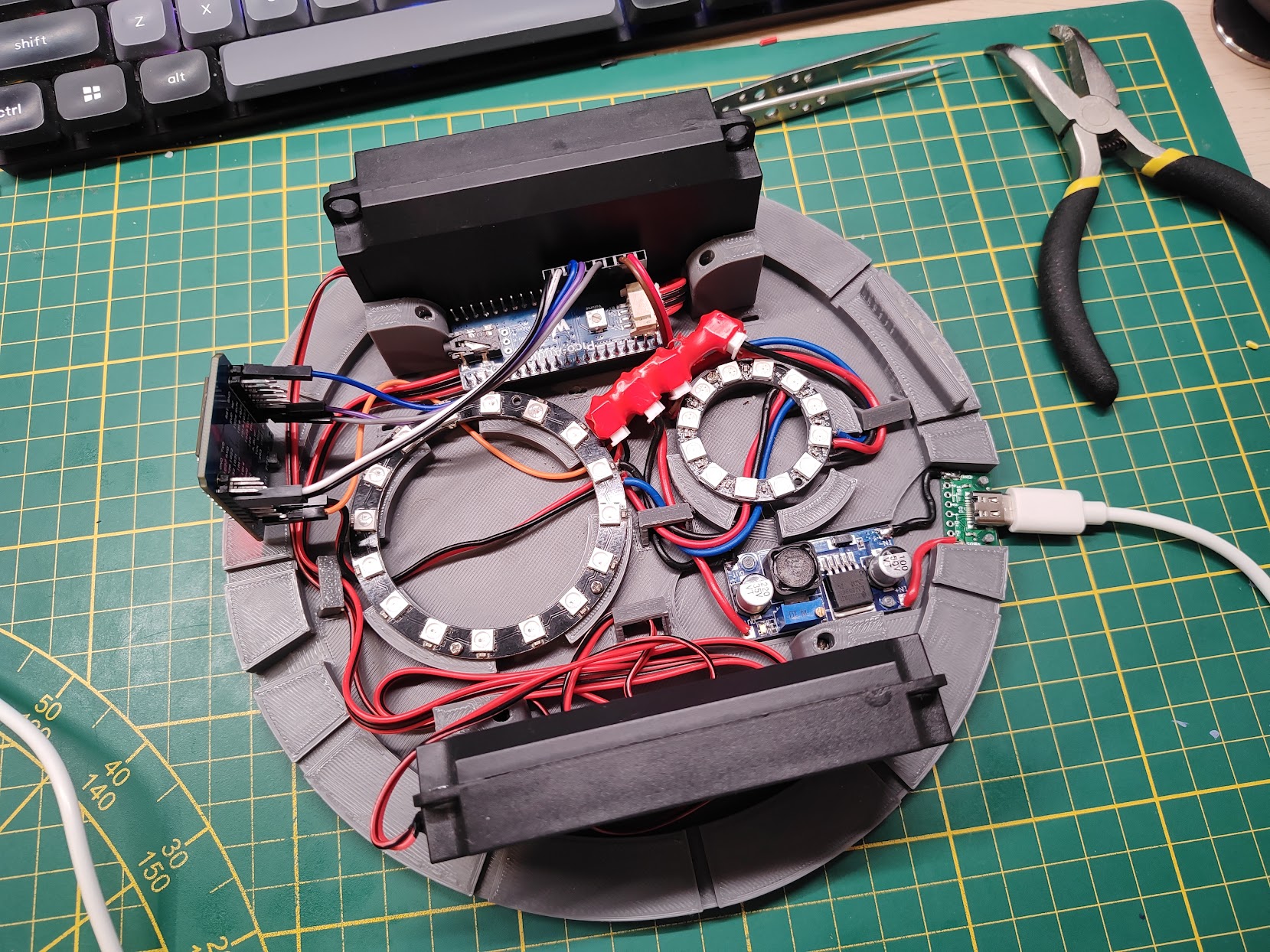
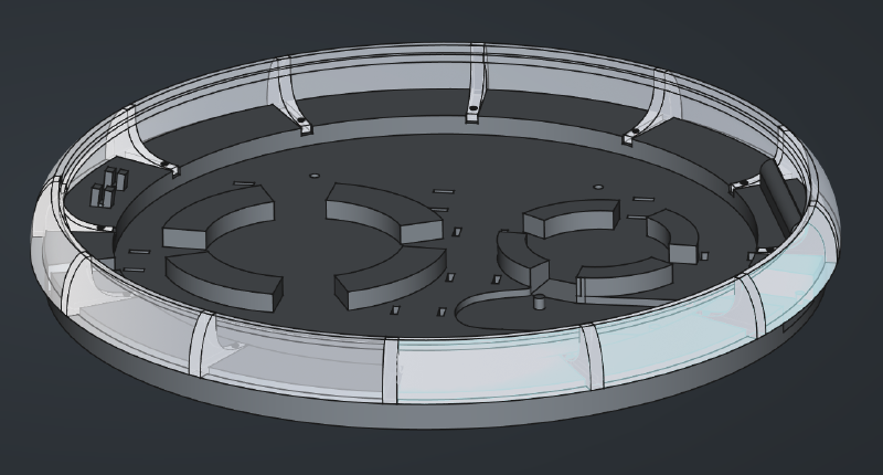
It was time to spend some quality time with FreeCAD. Idea was to make the figure stand on a base tall enough to house the speakers. As a bonus, a slightly taller base helps diffuse the lights so that the individual LEDs will not be as visible on the outside.
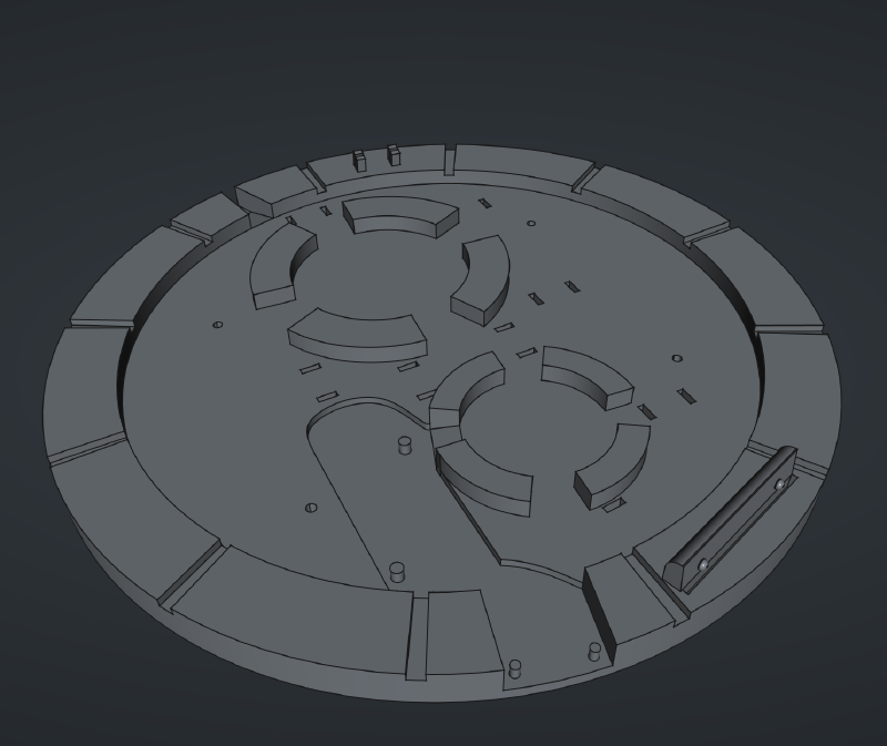
Tha base had places for the LED rings, small space for the power supply, embedded slightly in the print, cutouts for a USB-C connector, and notches around the circumference for the walls.
Mounted in the notches around the base there would be walls, 3D-printed from a semi-transparent PLA. Since the working area of my printer is too small to print the entire wall as a single part, I had to split it in four. This added some extra complexity, because all the parts will need to be tied together.
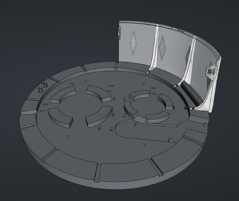
To make sure all the parts will fit this time, I tried to include all of them in the 3D model.
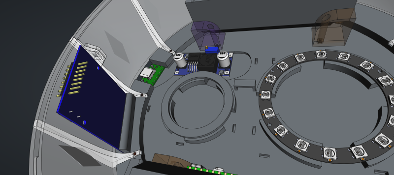
The small cutouts in the base are meant for routing wires through them, holding them in place with a small clamp.
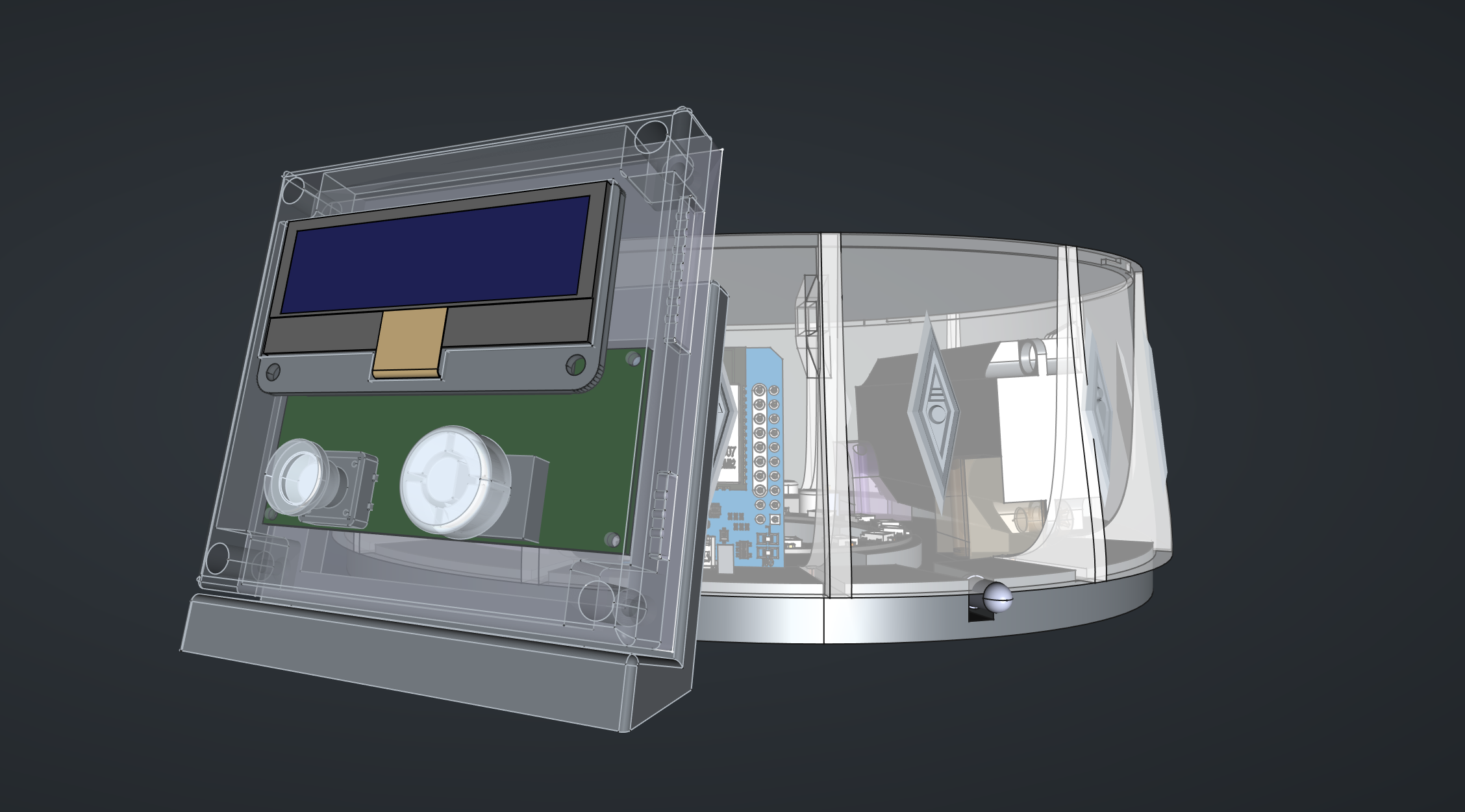
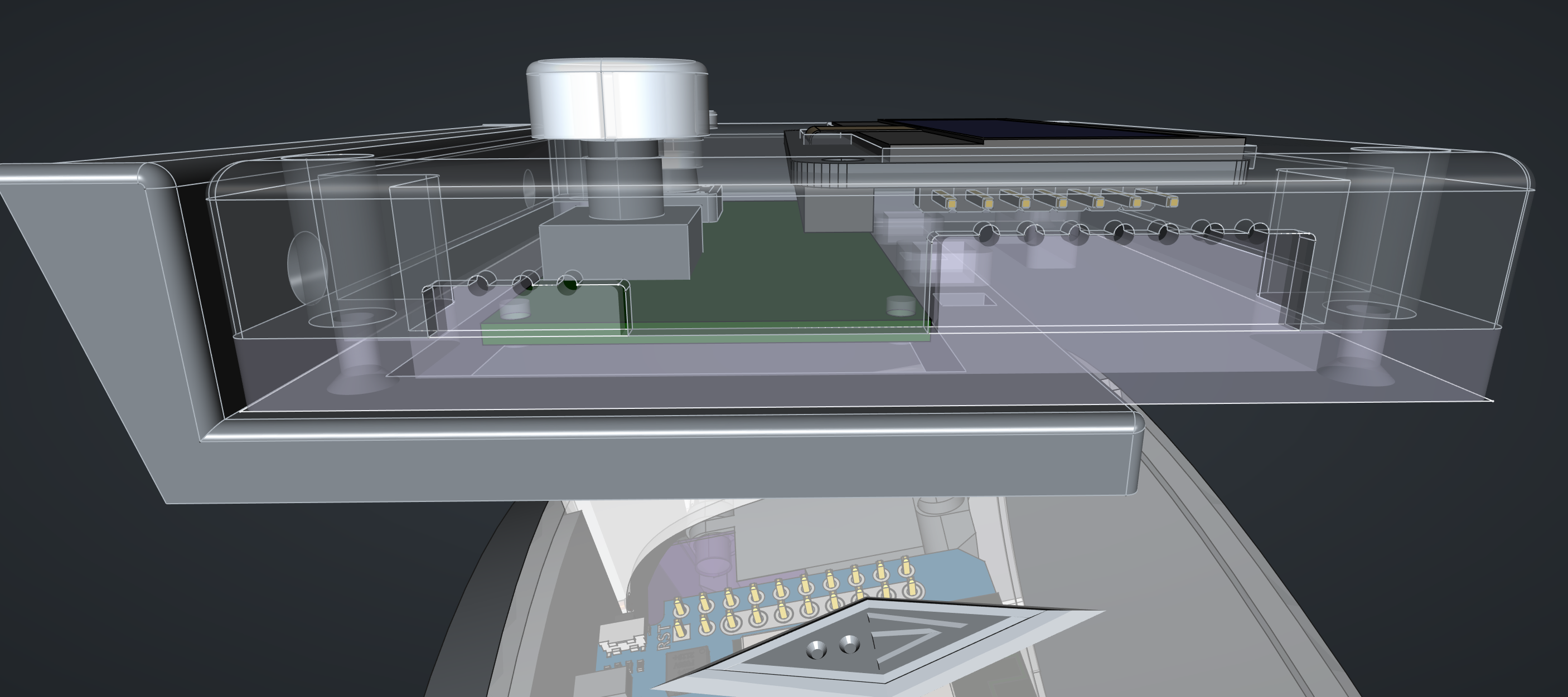
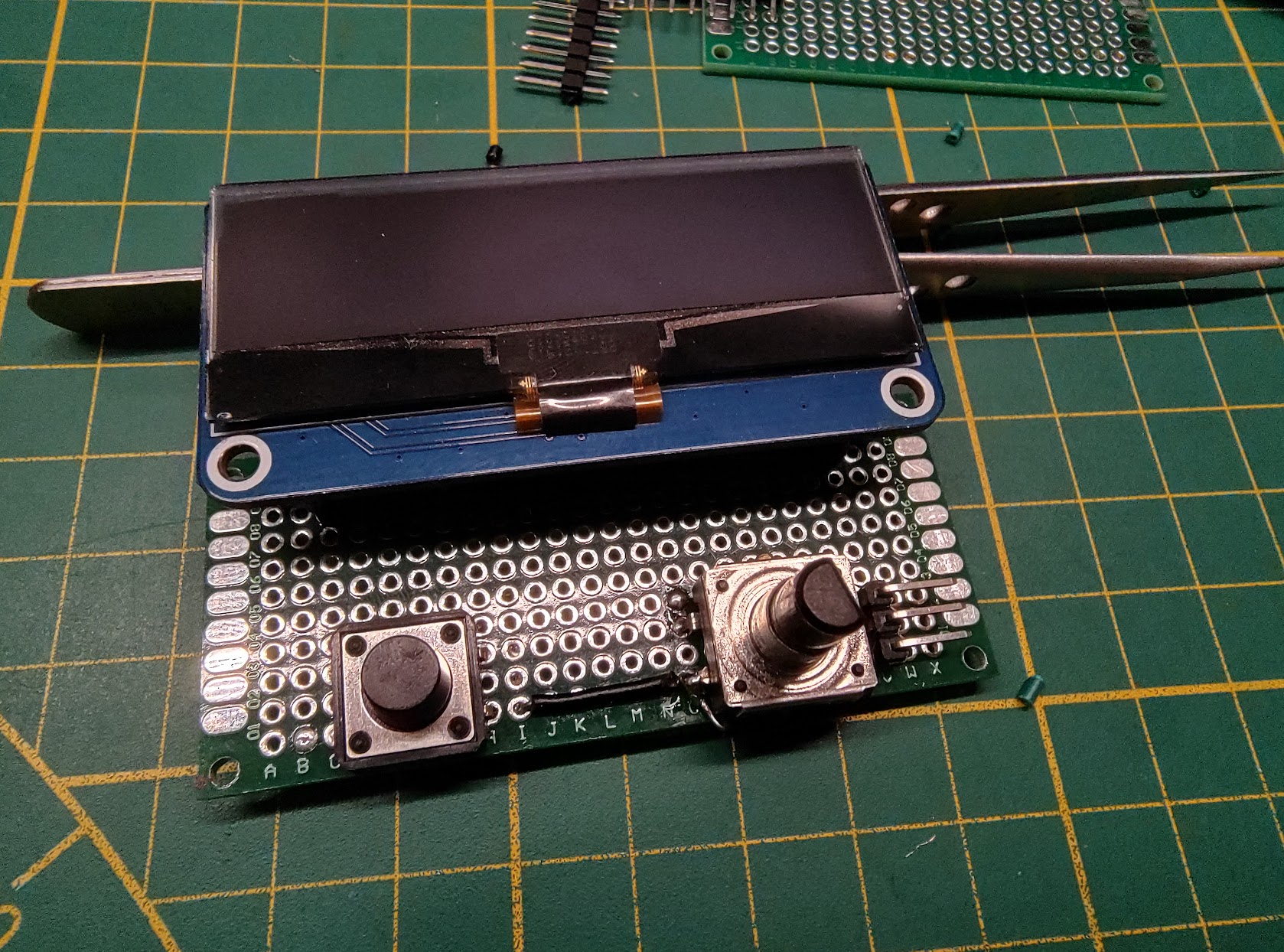
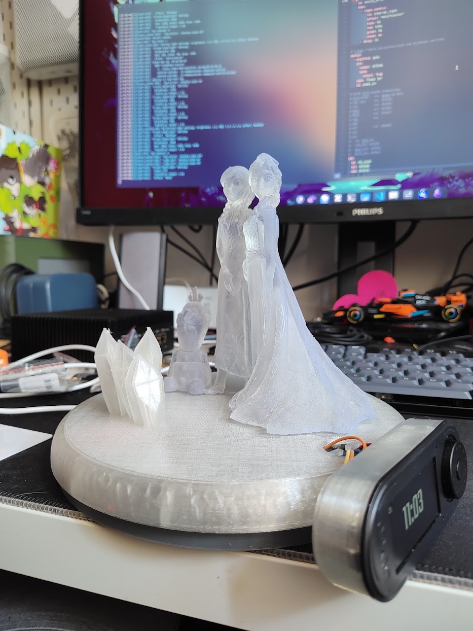
Screen migrated to an external controller assembly, with rotary encoder and push button for local control (all 3D-printed).
And hey, it worked! Still a bit of a wire spaghetti, but at least everything fits inside6.
Everything was ready for testing, and that’s the point in which this project hit a major bump: with ESPHome it is somewhat difficult to simultaneously drive an OLED screen, bunch of RGB LEDs, and stream music.
ESPHome components’ operation is blocking; handler for the next component will not start until the previous one had finished. And components may take a long time to complete their operations: display would take as much as 150ms to complete, RGB LED driver is consuming a lot of CPU time, especially when the rainbow light effect is on.
In worst case scenario, with the display and the rainbow light effect, any attempt to stream music would result in stuttering. Still, streaming music to the RFID Jukebox worked, just not well enough.
…a tag reader, maybe?#
At this stage, only thing to do was to try and salvage whatever could be salvaged. Maybe if not a full-blown jukebox, making this into a fancy RFID tag reader/night lamp/clock would be good enough7.
I still had a first version of the Muse Luxe speaker waiting to be set up. If it could be integrated into the Home Assistant, the whole RFID Jukebox would still work, only the speaker would be a device separate from the tag reader.
Okay then, let’s make a tag reader. In this case, the high walls of the case are not needed, it does not need to fit those bulky speakers. Lite version of it would do better. Fortunately, shrinking the walls in FreeCAD went smoothly.
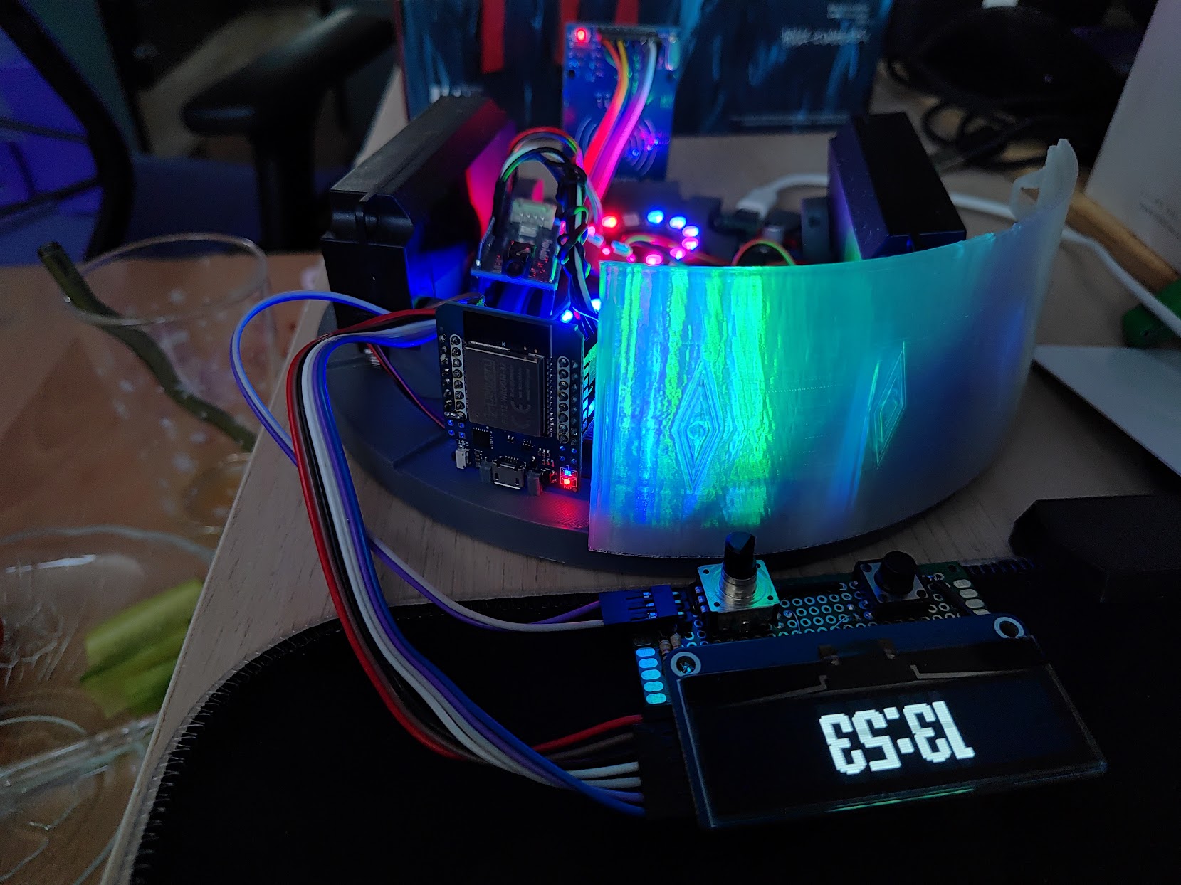
I also switched the trusty Wemos D1 board to a better fitting Lilygo T-Embed (not affiliated) module (good thing I had one…). Why is it better?
- integrates a button and a rotary encoder in a smaller form factor
- uses LED screen instead of OLED. Displaying only date, OLED screen would become burnt-in.
- comes with built-in microphone, enabling future usage as a voice assistant
- did I mention it’s smaller?
So, there we go, a night lamp/clock with an RFID tag reader, three years in the making, finally ready.
What did we learn today?#
Unless you're in it just for a journey, know your destination.
This is true for both hardware and software. To build something, a rough idea of what this "something" should look like is often not enough.
Know the use cases (
night light, media player, or just a tag reader?
), define requirements, figure out the minimum resources (how big should this case be?
), add some wiggle room (ooh, I should add buttons here, but where?
), build a good enough product (why cram speakers inside if I can just control a separate one?
).Of course, there's nothing wrong with being in it just for the journey. The entire hacker culture is built around this notion, and it gave the humanity some great things.
PCB is typically better than a spaghetti of wires.
Unless it isn't, because:
Spaghetti of wires is better than PCB if the PCB doesn't work.
All this is a specialization of:
If it's stupid but it works, it ain't stupid.
Do not design a case with a tight fit, because it won't fit.
It really won't. Tolerances were invented for a reason.Do. Not. Rush. To. The. Assembly.
This is true for soo many other things... Don't rush your project to deployment, those details really matter.
this was back in 2022, no need to rush to their website. ↩︎
Probably going out on adventures organized by the Missing Socks Travel. ↩︎
I was neither. ↩︎
Because why not? ↩︎
I wasn’t going to use an RPi Pico, but this module had the smallest footprint. ↩︎
Author will graciously skip a description of hours spent trying and failing to align the wires without breaking something. ↩︎
MVP, Minimal Viable Product, if you’re into startups. ↩︎